
21.12.11
15.12.11
Ενδιαφέροντα LINK
Γενική περιβαλλοντική πληροφορία, Προστατευόμενες περιοχές, απειλούμενα είδη, Υγρότοποι και υδρολογική πληροφορία, Δάση, Εδάφη – γεωλογία κλπ
Σημειώνονται ενδεικτικά ιστοσελίδες παρόμοιων χαρτογραφικών εφαρμογών που έχουν αναπτυχθεί από ελληνικούς και διεθνείς οργανισμούς. Οι υπεύθυνοι του Οικοσκόπιου θα φροντίζουν για την τακτική ενημέρωση αυτής της σελίδας κατόπιν αξιολόγησης προτάσεων και των επισκεπτών της, καταβάλλοντας κάθε δυνατή προσπάθεια ώστε οι συνδέσεις που προτείνονται να περιέχουν έγκυρη και κατά το δυνατόν πληρέστερη πληροφορία.
9.12.11
Gooman Jack Rock Mass Dilatometer Testing

Goodman Jack
The Goodman Jack is a borehole tool used for estimating the deformability of rock masses in-situ. It is designed to be used in 3" (76 mm) boreholes.
The Goodman Jack consists of a hydraulic jack with curved bearing plates, LVDT sensors, a displacement indicator, a hydraulic pump with pressure gauge, hydraulic hose, electrical cable, and a coupler for drill rod.
The jack is attached to drill rod and inserted into the borehole. A hand pump is used to create hydraulic pressure in the lines connected to the jack, which in turn activates the pistons and produces a uniform and unidirectional stress field at the bearing plate. The applied hydraulic pressure is measured with a standard Bourdon-type pressure gauge. The deformation of the rock is measured by two linear variable differential transformers (LVDT) and data are displayed by the indicator at the surface. After the test, the bearing plates are retracted by reversed pistons and the jack is withdrawn from the borehole.
The modulus of deformation is calculated using formulae derived empirically from in-situ testing and correction factors that were developed by laboratory testing.
1.12.11
Big Ben leaning "..... just about visible ....."
from  Thursday December 1, 2011 11:29 PM NZT

Whether the British parliament is leaning to the left or right depends on your point of view but Big Ben is officially tilting.
And surveyors say it is getting worse.
A new report has found the top of the famous clock tower, which stands above the parliament in central London, is now just under half a metre off the perpendicular.
That is so far off that experts believe the tilt is visible to the naked eye.
"The tilt is now just about visible," said John Burland, a senior research investigator from Imperial College London who has worked on Big Ben and the Leaning Tower of Pisa.
"You can see it if you stand on Parliament Square and look east, towards the river. I have heard tourists there taking photographs saying 'I don't think it is quite vertical' - and they are quite right," he told the Sunday Telegraph.
"If it started greater acceleration, we would have to look at doing something but I don't think we need to do anything for a few years yet."
Civil engineers believe the tower is sinking more quickly on the north side than the south side of the Palace of Westminster.
Monitoring instruments have suggested the tilt has increased by about a centimetre a year since 2003, about 40 per cent faster than the long-term average.
The tower is now leaning towards the northwest at an angle of 0.26 degrees, meaning the top of the tower is 43.5cm from vertical.
It would take another 4000 years or so for it to match the angle of the Leaning Tower of Pisa, which leans by about four degrees.
The problem has been blamed on decades of building work around the foot of the 96-metre, 11-storey structure since completion in 1858.
These have ranged from a sewer built for a tube line and an underground car park for MPs in the 1970s.


19.11.11
Phyllites - Φυλλίτες

Δείγματα ερευνητικής γεώτρησης βραχώδους σχηματισμού Φυλλιτών, ελαφρά αποσάθρωμενα, με οξειδώσεις, χαρακτηριστικές μικροπτυχώσεις - μικροδιαρρήξεις, και πυκνή χιλιοστομετρική σχιστότητα.
Rock core samples of Phyllite, slightly weathered, oxidized, with micro faults and fold. 
11.11.11
Fuschite mica - Φουξίτης

Fuchsite K(Cr,Al)2Si3AlO10(OH,F)2, is a chromium-rich variety of muscovite.
From rock core during the geotechnical investigation for Seix Sou Tunnel (Thessaloniki Greece).
Fuchsite is also an indicator that there an ultra-basic intrusion near by (peridotite).
From rock core during the geotechnical investigation for Seix Sou Tunnel (Thessaloniki Greece).
Fuchsite is also an indicator that there an ultra-basic intrusion near by (peridotite).


4.11.11
Neotectonic Normal fault

TUNNEL SUPPORT DESIGN USING EMPIRICAL METHODS
The development of empirical support design methods for the stability of underground project aim to include the experience gained from similar projects, in similar circumstances, in its construction. The main characteristic of these methods is the breakdown of a wider range of rock mass quality by matching each of these categories with various support measures. Moreover, in those support measures, the stages of excavation, and the presence of underground water, as well as stresses developed, where taken into account.
In order to estimate the geomechanical parameters of the rock mass, and the appropriate support measures, rock mass classification was performed following the Geological Strength Index method (GSI after Hoek - Marinos), Rock Mass Rating or Geomechanics classification (RMR after Bieniawski) and the Rock Tunnelling Quality Index (Q after Barton - NGI).
These classification systems help in grouping the rock mass into sections with similar geomechanical behavior based on qualitative and quantitative data measured on site. The analysis of these data leads to different classifications of each of the selected rock mass section, making possible to calibrate the final rock mass quality and the acquisition of the limits of variation of geomechanical parameters
These classification systems help in grouping the rock mass into sections with similar geomechanical behavior based on qualitative and quantitative data measured on site. The analysis of these data leads to different classifications of each of the selected rock mass section, making possible to calibrate the final rock mass quality and the acquisition of the limits of variation of geomechanical parameters
Bieniawski 1989 Method (Rock Mass Rating)
Bieniawski (1976) published the details of a rock mass classification called the Geomechanics Classification or the Rock Mass Rating (RMR) system. Over the years, this system has been successively refined as more case records have been examined, and the user should be aware that Bieniawski has made significant changes in the ratings assigned to different parameters. The discussion which follows is based upon the 1989 version of the classification (Bieniawski, 1989). Both this version and the 1976 version deal with estimating the strength of rock masses and the evaluation of the necessary support measures. One of the main advantages of the RMR classification seam is the easy of data collection needed to classify the rock mass. The following six parameters are used to classify a rock mass using the RMR system:
o Uniaxial compressive strength of rock material
o Rock Quality Designation (RQD)
o Spacing of discontinuities
o Condition of discontinuities
o Groundwater conditions
o Orientation of discontinuities
By applying this classification system, the rock mass is divided into a number of structural regions and each region is classified separately. The boundaries of the structural regions usually coincide with a major structural feature such as a fault or with a change in rock type. In some cases, significant changes in discontinuity spacing or characteristics, within the same rock type, may necessitate the division of the rock mass into a number of small structural regions.
The Rock Mass Rating system is presented in Fig B1, giving the ratings for each of the six parameters listed above. These ratings are summed to give a value of RMR. It should be noted though, that when applying and evaluating RMR a range of values must be introduced rather than a single RMR value, corresponding to the expected range of the typical rock mass parameters (upper and lower bound values principle).

Fig. Β1: Rock Mass Rating System (After Bieniawski 1989)
Using the basic RMR value, rock mass can classified in the following five categories (Fig. Β2). For each one of the above categories Bieniawski proposed a range of values for friction angle and cohesion, as well as the average stand up time where unsupported excavation can withstand (Fig. Β3).

Fig. Β2: Rock mass classifications, shear strength estimation and average stand - up time for unsupported excavation after Bieniawski (1989)

Fig. Β3: Relationship between effective span and stand - up time for each of the rockmass classification categories after Bieniawski (1974)
NGI Method 1974 (Q Rock Tunneling Quality Index)
By evaluating a large number of case histories of underground excavations, Barton et al (1974) of the Norwegian Geotechnical Institute proposed a Tunnelling Quality Index (Q) for the determination of rock mass characteristics and tunnel support requirements. The numerical value of the index Q varies on a logarithmic scale from 0.001 to a maximum of 1,000 and is defined by:

where:
RQD is the Rock Quality Designation
Jn is the joint set number, ranging 0.5 – 20
Jr is the joint roughness number, ranging 0.5 – 4
Ja is the joint alteration number, ranging 0.75 – 20
Jw is the joint water reduction factor, ranging 0.05 – 1
SRF is the stress reduction factor, ranging 0.5 – 400
In explaining the meaning of the parameters used to determine the value of Q, Barton et al (1974) offer the following comments:
o The first quotient (RQD/Jn), representing the structure of the rock mass, is a crude measure of the block or particle size.
o The second quotient (Jr/Ja) represents the roughness and frictional characteristics of the joint walls or filling materials.
o The third quotient (Jw/SRF) consists of two stress parameters describing the 'active stress'.
It appears that rock tunnelling quality Q can now be considered to be a function of only three parameters which are crude measures of:
1. Block size (RQD/Jn)
2. Inter-block shear strength (Jr/ Ja)
3. Active stress (Jw/SRF)
The source of identification of the necessary factor needed to evaluated Q is one field surveys. Moreover, in the extreme case where no borehole data are available, the range of RQD values can be estimated using the relationship introduced by Hudson - Priest (’79) and ISRM (’78), taking into account the mean discontinuity span (x) and Jv (sum of discontinuities per cubic meter of rock).
Hudson - Priest (’79) where λ=1/x
ISRM (’78)
Q values ranging from 0.001 to 1000 (Table C1) classifing the rock mass into several support categories (Fig. C1) after Barton & Grimstad (1994).
Q | Rock mass quality type |
0.001 ÷ 0.01 | Exceptionally poor |
0.01 ÷ 0.1 | Extremely poor |
0.1 ÷ 1 | Very poor |
1 ÷ 4 | Poor |
4 ÷ 10 | Fair |
10 ÷ 40 | Good |
40 ÷ 100 | Very good |
100 ÷ 400 | Extremely good |
400 ÷ 1000 | Exceptionally good |
Table C1: Rock mass quality types after Q

Fig. C1: Estimated support categories based on the tunnelling quality index Q (after Grimstad and Barton, 1993, reproduced from Palmstrom and Broch, 2006)


23.10.11
Barton - Bandis Shear Strength Estimation

Barton - Bandis shear strength estimation criterion for rockmass discontinuities (upper and lower bound approach and rock shear test data).
Rock masses contain discontinuities such as bedding planes, joints, shear zones and faults. The shear resistance along discontinuities, which governed the shear resistance of the rock mass, depends on acting normal stresses, interface lentgh, interface roughness etc. By measuring the shear strength of rock discontinuities of similar length, a significant variation occurs for the τ values, at low confinying stresses. The shear strentg criterion proposed by Barton make use of the following parameters to estimate the shear resistance and the shear strentgh parameters c (cohesion) and φ (angle of internal friction):
· basic friction angle (Φb) determined as the strenth resistance on smooth planar surface
· joint roughness coefficient (JRC)
· joint compression strength (JCS)
· probable filling material and its mechanical properties (such as clay gouge)
It should be also noted that the range of stength variation is reduced as the stresses are increased.
Hoek - Brown Failure Criterion

The criterion starts from the properties of intact rock and then introduced factors to reduce these properties on the basis of the characteristics of joints in a rock mass. The rock mass shear strength is estimated using the Hoek and Brown failure criterion (edition 2002), where rock mass is considered as homogeneous material and an average value is determind by fitting a linear Mohr - Coulomb relationship by least squares method.
In the above example a rockmass of conglomerate is considered, and taken into account the variation of data and parameters (upper and lower bound).
13.10.11

12.10.11
Massive rock slope failure (Cornwall cliff collapse)
http://www.bbc.co.uk/news/uk-15251292


Geologist Richard Hocking. who filmed a massive cliff fall in Cornwall, says it was the most exciting thing that he has ever seen.
Thousands of tonnes of rock fell into the sea at North Cliffs near Hayle two weeks ago - just days after part of the coastal footpath was diverted.
Mr Hocking, who is a soils and materials engineer for Cornwall Council, was there to assess the situation when the collapse happened. He had his camera with him and managed to capture the event on it.
7th class slope failure (after Cruden & Varnes '96)

7th class slope failure (after Cruden & Varnes '96)

8.10.11
Soil and Rock Slope Stability

Embankment slope stability analysis

Road cut stability determination with proposed stability measures (rock bolts)

6.10.11
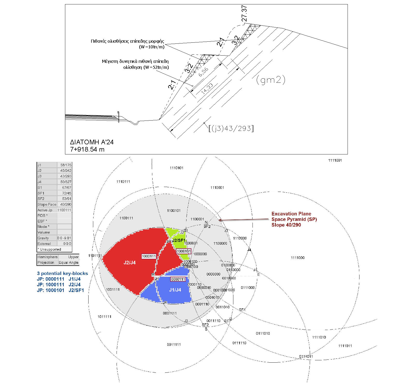
Rock slope stability - wedge failure

Απεικόνιση αποτελεσμάτων κινηματικών αναλύσεων ως προς σφηνοειδή ολίσθηση (wedge) για κάθε εξεταζόμενο πρανές και για κλίσεις 2:1 και 3:2
21.9.11
Methane and water jet after 25m

The area under investigation consisted of grey silty clay of high plasticity (CH - OH) with peat layers at various depth.
After 25m, a layer of more permeable silty sand (SM) give rise of gaz jet at the beginning, and after about 30min, silty sand together with water come out for at least 3 hours.
Geotechnical Cross Section - Road Cutting

γεωλογικές, γεωτεχνικές, τεχνικογεωλογικές, εδαφοτεχνικές, έρευνες, μελέτες, γεωλογικά, τεχνικογεωλογικά, εδαφοτεχνικά, γεωτεχνικά έργα, ερευνητικές γεωτρήσεις, εργασίες, έρευνα εδάφους, υπεδάφους, γεωλογική, τεχνικογεωλογική, εδαφοτεχνική, γεωτεχνική έρευνα, μελέτη, γραφείο, εταιρία, γεωτεχνικών, τεχνικογεωλογικών, εδαφοτεχνικών, γεωλογικών ερευνών, μελετών, ανόρυξη, δειγματοληπτικών, ερευνητικών γεωτρήσεων, βραχομηχανική, μελέτες ευστάθειας βραχωδών και εδαφικών πρανών, καταγραφή ερευνητικών γεωτρήσεων, επιτόπου δοκιμές, εδαφοτεχνική μελέτη, εδαφοτεχνική έρευνα, παράμετροι διατμητικής αντοχής, αντοχή βράχου, βραχοσφήνες, block theory
28.5.11
Taiwan Freeway No. 3 landslide probe finds likely causes
| Written by Randy Post (taken from http://geoprac.net/) |
| Wednesday, 13 April 2011 16:18 |
 A panel of experts in civil engineering and geotechnical engineering has completed their investigation into the failure of the slope above Freeway No. 3 in Taiwan last April that killed 4 people. Their forensic geotechnical investigations concluded that the dip slope was already marginally stable. But they noted that they found corroded steel ground anchors that were part of the retaining system meant to restrain the slope. They conjecture that even though the contractor followed the relevant standards at the time of constructions, somehow voids formed around the cable during the grouting process and made the cable susceptible to corrosion. A panel of experts in civil engineering and geotechnical engineering has completed their investigation into the failure of the slope above Freeway No. 3 in Taiwan last April that killed 4 people. Their forensic geotechnical investigations concluded that the dip slope was already marginally stable. But they noted that they found corroded steel ground anchors that were part of the retaining system meant to restrain the slope. They conjecture that even though the contractor followed the relevant standards at the time of constructions, somehow voids formed around the cable during the grouting process and made the cable susceptible to corrosion.Also noteworthy is that as a result of this failure, Taiwan's National Freeway Bureau has changed standards for grouting ground anchors. They also conducted a comprehensive survey of all slopes along freeways and identified 32 slopes that were placed on a priority list for monitoring and inspection and 17 were found to need some form of mitigation. [Source: Taipei Times. Image: Sulekha.com] |
Rock Slope Stability _ unstable rock treatment
from GeoPrac.net Monthly Newsletter #24 - 2011 April/May
http://geoprac.net/geonews-mainmenu-63/65-geologic-hazards/581-video-helicopter-based-rock-scaling-qsledgehammerq
There is a relatively new version of a video that came out in 2009 where the Norwegian Public Road Administration hired a helicopter to try to scale loose rock with a wrecking ball. This version has english subtitles explaining a few things, and also shows another technique they tried for scaling rock, water bombing!
Εγγραφή σε:
Αναρτήσεις (Atom)